electronics
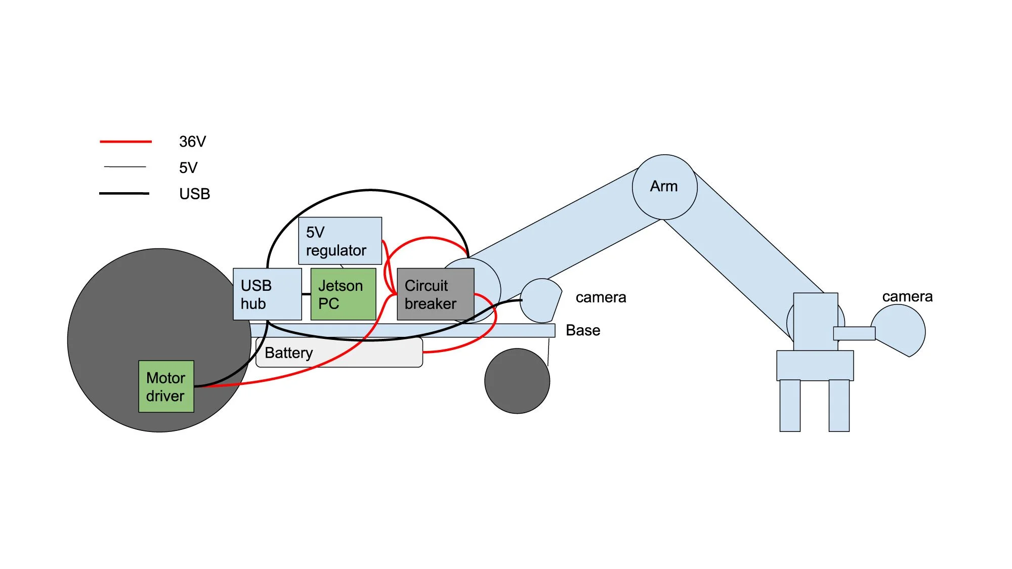
Here are some early wiring diagrams. Power and communication passes through the bore of the actuators for a clean exterior. The bore allows for running an additional Ethernet or other cable to the wrist. A single chassis/battery/digital ground shall be used to minimize noise. The joint boards will be designed with internal USB hub so they can be daisy chained as shown below.
In order to run the arm requires only 4 conductors, 2 for USB high speed (480 Mbps), which are ideally shielded, and 2 power cables.
CONNECTORS
The through bore in the arm allows for the pass through of some connectors. By selecting small connectors we can allow for crimping the cables outside the actuator and then assembling into the actuator. Connectors that will fit well are the Hirose DF57 for communication and DF61 for power. Inline connectors may also be used to ease disassembly and run larger gauge wire for long link runs. The crimps should be readily done for low cost with a multipurpose crimp tool such as the Engineer PAD-11.
Cables
In order to have good compatibility with the Hirose connectors we can use PVC insulated wire, 22 AWG for power and 28 AWG for USB. The PVC insulated cable diameters that must pass through the bore are 2 x 1.3 mm and 2 x 0.8 mm (unshielded) or 1 x 3.2 mm (shielded).


